HiSeq2000 - Next Level Hacking
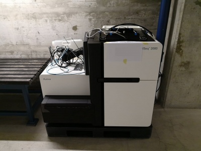
We got a HiSeq 2000, Next Level Sequencing Machine from the Genomics Facility of Department of Biosystems Science and Engineering in Basel. Contact through Biozentrum, University of Basel. We got it for free with the only disclaimer: "The biohackers should understand that they are responsible to organize and pay for the transport as well as that there is no warranty or support that can be given neither by us nor the DBSSE."
This type of machine seems to be quite difficult to get up and running and also reagents, flowcell-kits and software licences can be expensive. Since more of these machines seem to show up in second hand (there are new machine generations by Illumina) it would be worth trying to find a way to make them work. Sequencing for all.
Specifications:
https://www.illumina.com/documents/products/datasheets/datasheet_hiseq2000.pdf
The HiSeq2000 (200Gb) was introduced in the year 2010. Followed by HiSeq2500 (500Gb) in 2012. And HiSeq X Ten (1000Gb) in 2014. In 2017 the NovaSeq series of machines was launched.
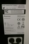
The machine is a quite early on, from March 2011, Serial Number is 700792, so the machine can not be updated to software and chemistry v4. Only machines with SN#
7001403 or higher can get the FPGA update v4.
Contents
- 1 First Inspection
- 2 Chemistry
- 3 Software
- 4 Workstation (Computer)
- 5 Software Installation
- 6 Using the System with Recycled Chemistry and FlowChips
- 7 Technical Descriptions / Findings
- 8 Optical System
- 9 Using the HiSeq2000 as aFluorescent Scanning Microscope
- 10 Links and Information
- 11 OpenSeq / Discussion
First Inspection
I made a first inspection on the machine. It seems very well made (2011). I still think it would be cool to make it run as is. It's basically a big microfluidic system. So if we get the pumps and the cameras to work we can hack it into anything we want 🙂. Even if it's not for sequencing - it's basically a holder for flow-cells with a fluorescence camera attached to it. And 16 channels with pumps and selector valves that attach to the flow cells. Plus a fridge and a computer.
And peltier for heating and cooling (pcr). Now trying to get the control software. I also think the system is "relatively" open... the software can be downloaded and kind of installs, there is no ID checking on the supplies or anything. Looks very hackable. Also all the cases can be opened easily. Let's do a weekend hack-session on it.
I think it's great opportunity to learn about next level sequencing and about how theses machines work.
Fluidic System:
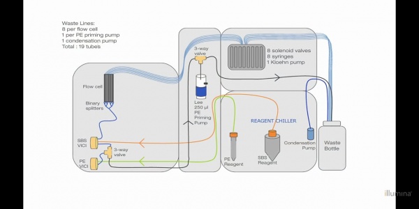
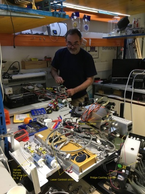
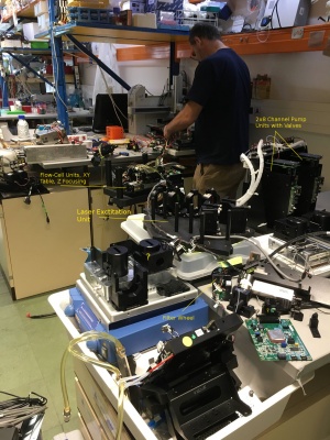
Some pictures from the inside of the machine:
Lausanne Bio-Hackerspace Hackuarium got a HiSeq2000 (SN# 700918) and Gustavo dissected it. Here some pictures that Rachel sent me with comments form what I think components are:
Chemistry
Some images describing the Illumina Next-Generation Sequencing Chemistry:
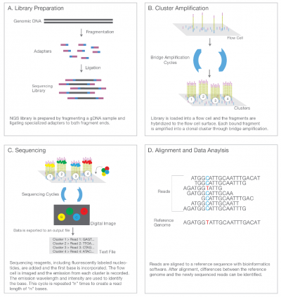
Illumina uses a process called "Sequencing-by-synthesis"
The HiSeq (and MiSeq) use 4-colour SBS
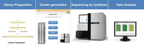
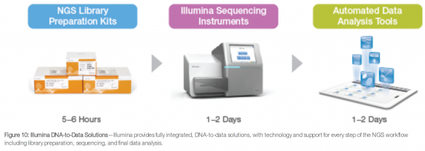
The full DNA to Data solution:
Paper on the 4 color SBS:
https://www.ncbi.nlm.nih.gov/pmc/articles/PMC1702316/
Video with the possibilities for library preparation:
https://www.youtube.com/watch?v=_yC0Bzw3WbQ
Library prep kit with sample purification by magnetic beads:
https://www.youtube.com/watch?v=UE1TAZZPUFI
The CBot 2 System is used to prepare the clusters on the flow cell:
https://emea.illumina.com/products/by-type/accessory-products/cbot.html
HiSeq (and TrueSeq) Rapid Cluster Kits can be clustered on the HiSeq (on-board cluster). They also seem to have a lower read and are cheaper:
https://emea.illumina.com/products/by-type/sequencing-kits/cluster-gen-sequencing-reagents/hiseq-rapid-cluster-kit-pe-sr.html
Chemisty Kits Option (running on our machine):
All Library Prep Kits
Cluster Generation (cBot needed):
- TruSeq SR Cluster Kit v3 - cBot-HS - Price: 4360 CHF
- TruSeq PE Cluster Kit v3 - cBot-HS - Price: 6674 CHF
- TruSeq Rapid SR and PE Cluster Kits, cBot Duo Cluster Kit - Price: Request
Maybe not compatible (for reference):
- HiSeq SR Rapid Cluster Kit v2, Price: 1002 CHF
- HiSeq PE Rapid Cluster Kit v2, Price: 1540 CHF
SBS Reagents:
- TruSeq SBS Kit v3 - HS (50 cycles), Price: 2552 CHF
- TruSeq Rapid SBS Kit - HS, Price: Request
Maybe not compatible (for reference):
- HiSeq Rapid SBS Kit v2 (50 cycles), Price: 587 CHF
Question:
- Are the "HiSeq Rapid Cluster Kit v2" compatible with HiSeq (before the v4 update). Or are the "TrueSeq Rapid Cluster Kits"?
- What Kit can be clustered on our HiSeq?
HiSeq Sequencing Protocol
PositionReagent Description
1	ICR (ICB)		Incorporation Mix Reagent			ViciPosition="1"
2	Water (PW1)		250 ml bottle with laboratory grade water	ViciPosition="2"
3	SMR			Scanning Mix Reagent 				ViciPosition="3"
4	SBS Buffer 1 (SB1)	High Salt Buffer				ViciPosition="4"
5	SBS Buffer 2 (SB2)	Incorporation Buffer				ViciPosition="5"
6	SBS Buffer 2 (SB2)	Incorporation Buffer				ViciPosition="6"
7	CMR			Cleavage Mix Reagent				ViciPosition="7"
8	SBS Buffer 3 (SB3)	Cleavage Buffer					ViciPosition="8"
FirstBase Incorporation
Pump SBS Buffer 2 (SB2) (5) - Incorporation Buffer
Delay 26 seconds
Flowcell Temp 55°
Pump ICR (1)- Incorporation Mix Reagent
Delay 26
Delay 80 seconds
Pump ICR (1) - Incorporation Mix Reagent
Delay 26 seconds
Delay 211 seconds
Flowcell Temp 20°
Pump SBS Buffer 2 (SB2) (5) - Incorporation Buffer
Delay 26 seconds
Imaging
Deblock
Pump SBS Buffer 3 (SB3) (8) - Cleavage Buffer
Delay 26 seconds
Flowcell Temp 55°
Pump CMR (7) - Cleavage Mix Reagent
Delay 26 seconds
Delay 80 seconds
Pump CMR (7) - Cleavage Mix Reagent
Delay 26 seconds
Delay 80 seconds
Pump CMR (7) - Cleavage Mix Reagent
Delay 26 seconds
Delay 80 seconds
Buffer Wash
Pump SB2 (6) - Incorporation Buffer
Delay 26 seconds
Pump SBS Buffer 1 (SB1) (4) - High Salt Buffer
Delay 26 second
Pump SB2 (6) - Incorporation Buffer
Delay 26 seconds
Pausing
Pump SBS Buffer 2 (SB2) (6) - Incorporation Buffer
Delay 25 seconds
Flow Cell A (BC001ACXX), Cycle #1
Chemistry FirstBase, Incorporation
Selecting Reagent SB2 (5)
Opening shutoff valve
Pumping Reagent SB2 (5), Aspirating port PortB
Delay 26 seconds
Pumping Reagent SB2 (5), Dispensing port PortC
Closing shutoff valve
Flowcell Temp 55°
Selecting Reagent ICB (1)
Opening shutoff valve
Pumping Reagent ICB (1), Aspirating port PortB
Delay 26
Closing shutoff valve
Delay 80 seconds
Selecting Reagent ICB (1)
Pumping Reagent ICB (1), Aspirating port PortB
Delay 26 seconds
Pumping Reagent ICB (1), Dispensing port PortC
Closing shutoff valve
Delay 211 seconds
Flowcell Temp 20°
Selecting Reagent SB2 (5)
Opening shutoff valve
Pumping Reagent SB2 (5), Aspirating port PortB
Delay 26 seconds
Pumping Reagent SB2 (5), Dispensing port PortC
Closing shutoff valve
Imaging
Imaging, Resuming Chemistry
Chemistry, Selecting Reagent SRE (3)
Opening shutoff valve
Pumping Reagent SRE (3), Aspirating port PortB
Delay 26 seconds
Pumping Reagent SRE (3), Dispensing port PortC
Closing shutoff valve
Flowcell Temp 20°
Waiting for imaging module
Imaging, Top Surface
Imaging, Top Surface, Aligning
Imaging, Top Surface, Aligning, Tilt
Imaging, Top Surface, Aligning, Tilt, Programming Camera
Imaging, Top Surface, Aligning, Tilt, Resizing Image
Move Emission Filter 11(sim) to OutOfPath
MoveSendTrigger Z Motor
Cycle #1, Imaging, Top Surface, Aligning, Tilt, Imaging, Frame #3
Copying Images
Aligning, Tilt, Saving focus image
Move EmissionFilterSet1(sim) ('A') to 'Bandpass2'
Handling Template Image C001
Frame #697
Saving Thumbnail Image
Image Analysis Flow Cell A 01, ImageProcessing, ProcessEarlyCycleAnalysis
CameraTDI Cleanup
Wait for frames then close excitation filters
Move Excitation Filter 2 to 'BlockPosition'
Flow Cell A (BC001ACXX), Cycle #1, Imaging, Bottom Surface, Lane 8, Swath 3 - X = 25.46642 Y = 93.43, Channels A, G, T, C, Scanning
Dither Clean Up Command
DitherPostSwathFocusCleanup
LookupFocusTrackingCleanup
Cycle #2, Chemistry CompleteCycle
Deblock
Cycle #2, Chemistry CompleteCycle, Deblock
Deblock, Selecting Reagent SB3 (8)
Deblock, Opening shutoff valve
Pumping Reagent SB3 (8)
Pumping Reagent SB3 (8), Aspirating port PortB
Delay 26 seconds
Pumping Reagent SB3 (8), Dispensing port PortC
Closing shutoff valve
Flowcell Temp 55°
Deblock, Selecting Reagent CMR (7)
Opening shutoff valve
Pumping Reagent CMR (7), Aspirating port PortB
Delay 26 seconds
Closing shutoff valve
Delay 80 seconds
Deblock, Selecting Reagent CMR (7)
Pumping Reagent CMR (7), Aspirating port PortB
Delay 26 of 26 seconds
Closing shutoff valve
Delay 80 of 80 seconds
Selecting Reagent CMR (7)
Pumping Reagent CMR (7), Aspirating port PortB
Closing shutoff valve
Delay 80 of 80 seconds
Buffer Wash
Buffer Wash, Pumping Reagent SB2 (6), Aspirating port PortB
Delay 1 seconds
Closing shutoff valve
Selecting Reagent SB1 (4)
Opening shutoff valve
Pumping Reagent SB1 (4), Aspirating port PortB
Delay 26 second
Pumping Reagent SB1 (4), Dispensing port PortC
Closing shutoff valve
Selecting Reagent SB2 (6)
Opening shutoff valve
Pumping Reagent SB2 (6), Aspirating port PortB
Delay 26 seconds
Closing shutoff valve
Incorporation
Flowcell Temp 55°
Incorporation, Selecting Reagent ICB (1)
Opening shutoff valve
Pumping Reagent ICB (1), Aspirating port PortB
Delay 26 seconds
Closing shutoff valve
Delay 80 of 80 seconds
Selecting Reagent ICB (1)
Pumping Reagent ICB (1), Aspirating port PortB
Delay 2 of 26 seconds
Closing shutoff valve
Delay 211 of 211 seconds
Flowcell Temp 20°
Selecting Reagent SB2 (6)=
Pumping Reagent SB2 (6), Aspirating port PortB
Delay 16 of 26 seconds
Closing shutoff valve
Pausing
Chemistry, Selecting Reagent SB2 (6)
Pumping Reagent SB2 (6), Aspirating port PortB
Delay 25 of 26 seconds
Closing shutoff valve
Software
Control Software
Our machine with SN# 700792 can not be updated to HiSeq Control Software (HCS) v2.2.37 or higher.
Possible options are (depends on software on the FGPA, how to find out?):
- HCS v1.5, RTA v1.13
- HCS v2.0, RTA v1.17
- HCS v2.2.38, RTA v1.18 - Not compatible
- HCS v2.2.58, RTA v1.18 - Not compatible
On the "do not eject" virtual drive from the machine it looks as if the last update was:
override_2013-08-21__05_11_55.cfg
So that was just after releas of HCS 2.0
The HiSeq instrument computer employs 64-bit Windows Vista.
Question:
- Does V2.0 have a Rapid Run mode?
- What is the "Include_Override.cfg" file?
Download for hcs_1-5-15-1:
https://support.illumina.com/downloads/hcs_1-5-15-1_rta_1-13_sav_1-8_software.html
Download for hcs_2_0_12:
https://support.illumina.com/downloads/hcs_2_0_12.html
Cropping and Stitching of Scans
https://github.com/orangeman/micro-art
Workstation (Computer)
Dell Precision T7500 Tower-Workstation
AMD FirePro V3750 256MB
48 Giga Ram
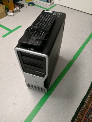
http://euro.dell.com/content/products/productdetails.aspx/workstation-precision-t7500?c=de&l=de&s=corp
http://www.dell.com/support/article/us/en/4/sln291329/precision-t7500-windows-xp-and-windows-vista-driver-install-guide?lang=en#Broadcom57XXGigabitControllerDriver
All the drives were removed from the computer when we got it. There is a raid controller board, an ethernet card and the Phoenix Video Card installed in the machine.
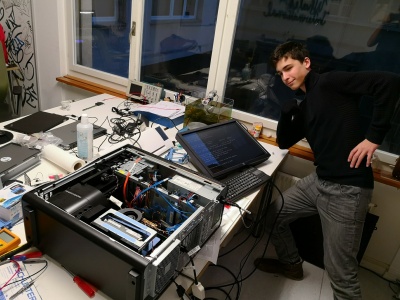
Unfortunately the computer has a problem with the power supply and does not start up properly and we need to press the button on the powersupply to get it going somehow.
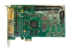 The Phoenix PCI Express x1
The screen comes with a touch screeen interface.
Software Installation
We had to completely reinstall the control computer. All the files needed to get the machine up and running could be found (2018) as free downloads on the internet. Here is how:
- First install Windows Vista
- Install the ethernet driver, the grafics card driver and the Chip-Set Driver from the Dell Support Hompage (links below)
- Install the HiSeq Controll software (in our case we guessed Version HCS 2.0, depends on the FPGA version and SN of the machine) using the install.bat
- The connect the HiSeq and turn it on, wait for 2 minutes until all the serial device show up
- Then had to install the FTDI2xx64 driver for the USB serial ports from the FTDI website (for Windows Vista)
- Also had to put a copy of the FTDI2XX.dll in the Illumina/ControlSoftware folder. (why?)
- Install the Camera driver DCAM-API v15.10.4787, https://dcam-api.com/downloads/
- Reboot
- Also put a copy of the camera.dll into the Illumina/ControlSoftware folder (not sure if needed).
- Then the software keeps asking for an "Override" file on C:, so I copied to "Override_xx" file from the "DONOTEJECT" drive of the machine to C: and renamed it to "override.cfg"
- Also the software needs drives up to E: for data / setting storage (just used some USB sticks)
- Then start the control software and wait for the initialization to complete.
After many tries the successfully initialized machine interface:
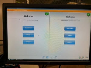
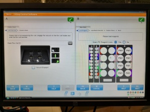
Ready for some sequencing (or further tests)
DCAP-api Driver:
https://dcam-api.com/downloads/
USB / Serial Port Sniffer that can be useful to reverse engineer the communication:
https://freeusbanalyzer.com/
https://docs.microsoft.com/en-us/sysinternals/downloads/portmon
Using the System with Recycled Chemistry and FlowChips
We were able to get some SBS chemistry (V4) and some used chip form a sequencing lab (Unil Lausanne). For every run that labs do there is about 15-20% chemistry left over and as there is only one flow chip contained in each kit, the chemisty can not usulay be used anymore. We also got some used flow chips that were allready processed. We managed to load the cheistry into our machine and start a sequencing run. (even thoug our machine is not suitable for V4 chemistry). The machine would first do a lot of pupming, then adjust to focus of the microscope in the corners of the flow chip and then start scanning the flow chanels by tiles and using the different lasers.
We set the software to store the scanned images:

Dumped (compressed) image showing fluorescence of T bases.
Challenge: If there was a way to 'clean' to reuse them, cheap DIY sequencing would be possible usine left over chemistry and chips collected from a sequencing lab.
Technical Descriptions / Findings
The fluorescent readout system with lasers and CCD cameras
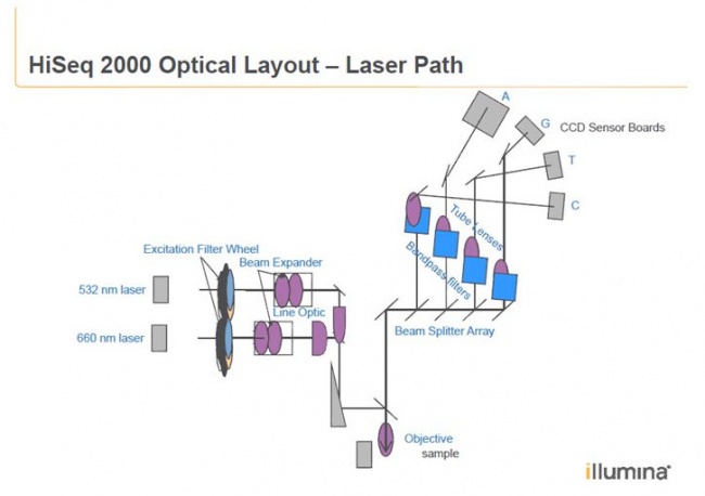
Patent by Illumina:
https://www.google.com/patents/DE202011003570U1?cl=it
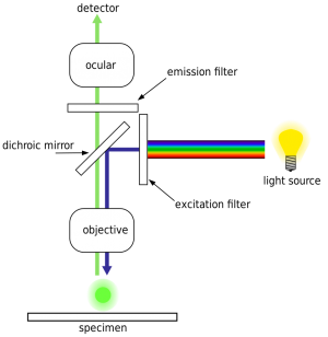
The HiSeq uses an epifluorescence microscope design shown in the diagram. Light of the excitation wavelength is focused on the specimen through the objective lens and the fluorescence emitted by the specimen is focused back the detector by the same objective.
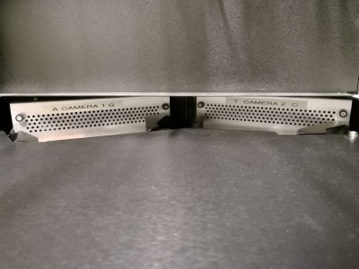
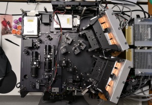
Here you can see the two camera units with even the letters A G T C written on it.
The laser calibration sheets that came with the machine:
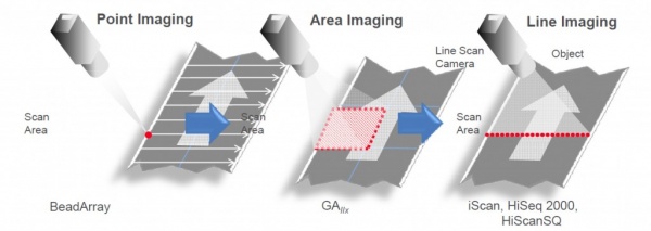
The readout system of the HiSeq uses Line Imaging:
The Flow-Cell
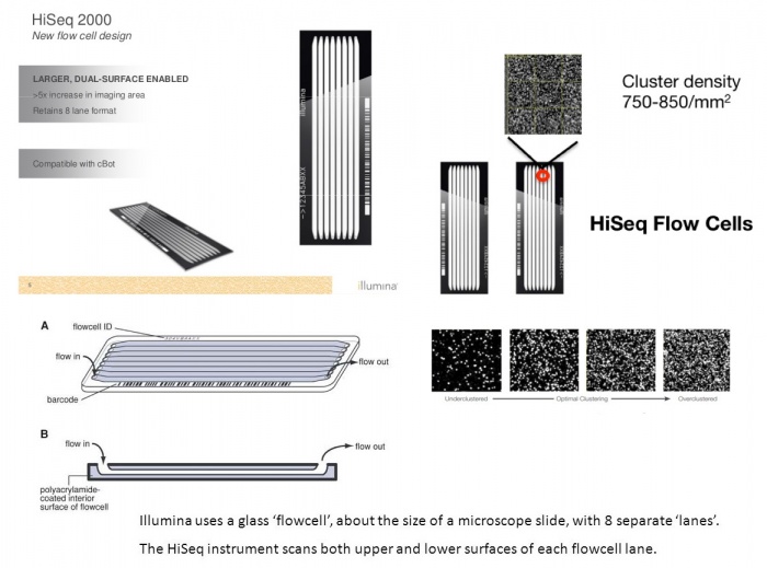
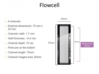
The recommended maximum cluster density is 750,000-850,000 clusters/mm² when using Illumina's v3 cluster generation and sequencing reagents in combination with HCS v1.4. That makes 866²-921² clusters or 1.08-1.12 um² in average per cluster.
Some rough calculations/estimations on what is going on in the machine
The DNA clusters are about 1 Micrometer in size. (or bigger for older machines/software, maybe 2-5 um)
The lines on the flow cells are about 1 mm large what means 1000 clusters. (Or lager, up to 1.7 mm)
The reading speed is about 1mm per second or 1000x1000 clusters per second. Or 1 Mega bases.
The lines are 6 cm long and there are 10 lines per flow cell.And two flow cells.
The means 600 Mega Clusters (Bases) per flowcell per complet run. And that takes about 600 seconds or 10 minutes.
Then flush the flow-cell to add the next base (SBS, sequencing by sythesis). Then start over again.
Unitl the whole 150 bases long DNA sequences are read.
This takes about 4 days... 10 Genoms.
The cluster are red in 4 colors / letters at the same time through 2 lasers exciting 4 colors in fluorescence.
By 4 CCD line cameras with Time delay and integration (TDI). Line cameras with 1 micrometer resolution, 1000 lines a second. Or 1 picture 1000x1000 per second...
The chemistry cost some hundreds to some thousands... but for what it does its not so bad. And you get the chemistry kit with the flowcell. So all the magic and the rest is just some kind of state of the art open hardware 🙂
Hardware components
Nice description on what hardware components are used in the HiSeq on the following page (see comments):
https://blogs.swarthmore.edu/Illumina+GAIIx+Teardown/?p=125#comments
- two lasers (Laserquantum ignis 660nm, gem 532nm with SMD6000 drivers)
- filter revolvers, beam expanders (Linos 2-8x) followed by a barrel lenses for each wavelength, a combiner to join the two excitation wavelengths
- piezo actuator for the Z-Stage (Physik Instrumente P-601 with driver E-601 and E-801 Sensor module)
- Nikon CFI Plan APO VC 20x Objective.
- XY-table (Parker 803-4099, something like the XR400 series, driven by a ViX-250-IH driver module).
- The “Docking Station” with the Flowcells are mounted on three Stepper adjustable points to align them with the focal plane of the line scanner.
- The fluorescence signal is divided by a fixed filter set 4x
- 4 CCD cameras with S10405 line CCDs from Hamamatsu (DIL 40 package).
- Two Hamamatsu Camera Control Boards (Model C10000-509) are each controlling two of these line cameras.
- Illumina board with: line CCDs -> 8 LTC2203 25Msps 16-Bit ADCs -> Altera Cyclone II FPGA. Spartan XC3S4000 FPGA and XC95288 CPLD (both Xilinx)
- Data is collected by the Phoenix AS-PHX-D48CL Frame grabber card in the Computer
- 3-Port Latching Valve Type:LHLA0531311H
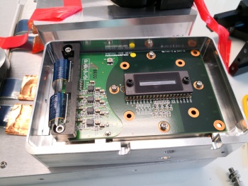
Hamamatsu TDI Line Camera Chip from the HiSeq
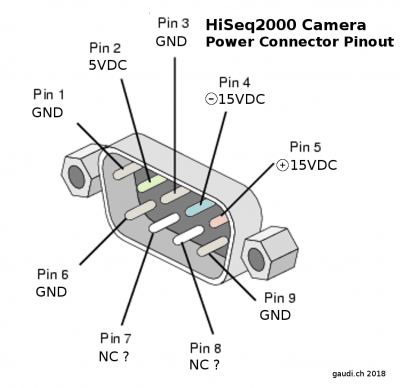
HiSeq2000 TDI camera power connector pin-out
3-Port Latching Valve Type:LHLA0531311H
The Lee Company
Ported: Conventional and Lo-Lohm Models
Voltage (Vdc) 5
LOHM RATE1 ON AIR AT 70°F (21°C) 1100 Lohms 7.32 SLPM @15 psid; Ref. Cv = 0.018)
Operating Pressure: Supply Vac - 45 psig
Differential 15 psid (max.) 5.5
Seal Material: Silicone
Plunger Head: PPS
Armature / Plunger Stop: FeCr Alloy4
Port usage
| Device | Port | Settings |
|---|---|---|
| ARM9BoardSerialPort / ARM9 Chem | Port: COM3; ARM9CHEM ;CM00006 | 115200 baud |
| ARM9BoardDiagSerialPort / ARM9 Diag | Port: COM6; ARM9DIAG | |
| ARM9PEPort (PCIO) Board | Port: COM4; PCIO (com_port_num) | 115200 baud |
| FPGA P1 Command / command_com_port_num | Port: COM10; IL000004 | 115200 baud |
| FPGA P2 Response / response_com_port_num | Port: COM11; IL000005 | 115200 baud |
FlowcellFluidics1 |
||
| FtdiViciValve1 / VICI A1: | Port: COM16; VICIA1 ;CM00004 | 9600 baud (19200?) |
| FtdiViciValve2 / VICI A2: | Port: COM20; VICIA2 ;CM00043 | 9600 baud |
| KloehnControllerPump / Kloehn A | Port: COM18; KLOEHNA ;CM00001 | 9600 baud |
FlowcellFluidics2 |
||
| FtdiViciValve1 / VICI B1: | Port: COM17; VICIB1 ;CM00002 | 9600 baud |
| FtdiViciValve2 / VICI B2: | Port: COM21; VICIB2 ;CM00044 | 9600 baud |
| KloehnControllerPump / Kloehn B | Port: COM19; KLOEHNB ;CM00003 | 9600 baud |
Laser 1,Green532,Smd6000 |
Port: COM12; IL000006 |
9600 baud |
| Laser 2,Red660,Smd6000 | Port: COM13; IL000007 | 9600 baud |
XMotor_MDrive_5mm (X-Stage). Manuals: 1 2 |
Port: COM7; IL000001 |
9600 baud |
| YMotor_VixServoIH_10nm (Y-Stage) / Servo linear motor MT49420. Programming Manual | Port: COM8; IL000002 | 9600 baud |
| Z-Stage | Port: COM9; IL000003 | |
Barcode_Reader |
Port: FTE2V9ML ; COM5 (com_port_num = 4) |
|
| PTC | Port: COM2 (com_port_num = 1) | 9600 baud |
| rs232 | Port: COM10 (offset 9) | |
| Test Port | Port: IL000010 | |
| PC Camera Ctrl | Port: COM14; IL000008 | |
Phoenix Cam 1? / AS-PHX-D48CL-PE1 (C10000-509) |
Port: COM22 |
|
| Phoenix Cam 2? / AS-PHX-D48CL-PE1 (C10000-509) | Port: COM23 | |
| Flash Drive | Port: COM15; IL000009 |
Scanner.ChemistryModule
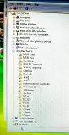
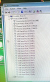
During the software install I got this rather interesting list on the Hardware Manager showing all the device names.
After the installation of the USB serial port driver the names disappeared.
Ports:
- ARM9 Chem
- ARM9 Diag
- Flash Drive
- FPGA P1 Command
- FPGA P2 Response
- Kloehn A
- Kloehn B
- Laser 1
- Laser 2
- Multimedia Video Controller ?
- PC Camera Ctrl ?
- PCIO Board
- Test Port ?
- VICI A1
- VICI A2
- VICI B1
- VICI B2
- X-Stage
- Y-Stage
- Z-Stage
Drives
Data (D:) Data (E:) DVD (F:) Removable (G:) DoNoEject (H:)
Comands
The HiSeq commands were extracted form the Control Software Log files . This file is created with every action of the software and contains a lot of information on what is going on, including the commands sent to the different devices via virtual serial port, set values and feedback from the machine. In the archive some logs including two (partial) sequencing runs. There is one spreadsheet with more extracted commands and one that shows the machine initialization sequence commands.
FPGA
Main controll unit with a Field Programmable Gate Array (FPGA).
| Command | Receive | Parameter | Function |
|---|---|---|---|
| FPGA Board | |||
| MISCRVC\n | MISCRVC 3.0.14 | Reads version number of a board C | |
| MISCRV\n | MISCRV 3.10.3 | Reads version number of a board | |
| RESET\n | @LOG The FPGA is now online. Enjoy! / RESET | Reset And Cancel All Commmands, is about to reset FPGA | |
| LED Bar | |||
| LEDMODEs m\n | LEDMODEs | s=[1,2] m=[0-7] 0=off, 1=yellow, 2=pulse yellow, 3=green, 4=pulse green, 5=blue, 6=pulse blue, 7=nightrider (sweep) blue |
Big front LED-bar light mode. s=1 left, s=2 right section (for each flow cell) |
| LEDPULSRATE r\n | LEDPULSRATE | r=[1-255] (milliseconds) | Puls rate of LED-bar. Controls, the frame update rate for the pulsing animation. |
| LEDSWPRATE r\n | LEDSWPRATE | r=[1-255] (milliseconds) | Sweeping rate of LED-bar. Controls, the frame update rate for the sweeping animation. |
| LEDMODETMPST 0\n | LEDMODETMPST | 0 = single mode / 1= Full size blue nightrider sweep. | Special LED nightrider mode |
| Emission Filters | |||
| EM2VL_DN p\n | EM2VL_DN | p=[9..91 / 10,20,40] (percent) | Emission Filter 2, Down Velocity (Percent) (Down=out of path, really is up) |
| EM2VL_UP p\n | EM2VL_UP | p=[9..91 / 10,20,40] (percent) | Emission Filter 2, Up Velocity (Percent) (Up=in of path, really is down) |
| EM2RDV_DN\n | EM2RDV_DN v | v = [9..91] 10 | Emission Filter 2, Read Down Velocity |
| EM2RDV_UP\n | EM2RDV_UP v | v = [9..91] 10 | Emission Filter 2, Read Up velocity |
| EM2O\n | Move filter Out of Path | ||
| EM2I\n | Move filter In of Path | ||
| EM2RD\n | EM2RD 0 1 0 0 | a b c d =[0,1] / a= , b=inPathSensor , c=OutOfPathSensor , d= / position = IntoPath / OutOfPath / Unknown | Read Filter Position (Sensor) |
| Excitation Filters | |||
| EXsHM2\n | EXsHM2 | s=[1,2] filter path | Home excitation filter 1 or 2 to laser-safe blocked position. |
| EXsMV p\n | s=[1,2] p=[-71,71] (OD0.4) / 270.0000 degrees / 71 Moved 'Reflective' to index 2 (OD2.5) 90 degrees | Move Excitation Filter Wheel by p (71 = 90 degrees 35.5=1 step? | |
| EXsVL p\n | s=[1,2] p=[131072] | Set Excitation Filter Wheel speed? | |
| EXsCUR p\n | s=[1,2] p=[35] | Set Excitation Filter Wheel Current? | |
| Tilt Motor Control | |||
| TnMOVETO p\n | T1MOVETO 18504 | n = [1,2,3] (motor), p=[0..ca.34300] (6560 steps / mm) 0 = all down / (steps, 656 steps/mm)? / (3025 steps (4.610 mm)? | Tilt motor (n) closed-loop absolute encoder moves. (Home Motor and Clear Register before use) |
| TnRD\n | TnRD q | n = [1,2,3] (motor) q=steps ?encoder und motor steps equal? | Read tilt motor encoder. |
| TnVL p\n | T1VL | n = [1,2,3] (motor) p=62500 | Tilt motor (n) set velocity ? |
| TnCUR 35\n | TnCUR | n = [1,2,3] (motor) p=35 | Motor Current? |
| TnCR | T1CR | n =[1,2,3] | Clear Counter Register of Motor Encoder |
| T1HM | T1HM / @TILTPOS3 p | n = [1,2,3] (motor) / p=steps | Tilt motor (n) homing. |
| Doors | |||
| DOORSSTATE p\n | DOORSSTATE | p=[0,1] | Set door state ? |
| DOORSOPEN\n | |||
| Laser Control | |||
| LASERPB p\n | LASERPB p | p=[0..255/500/or more] (DAC/mW?) | Set laser power. |
| SWLSRSHUT p\n | SWLSRSHUT | p=[0,1] Closing / Opening laser shutter | controls laser shutter |
| LSEN\n | LSEN | Laser Safety Enable Reporting | |
| TDI Control (Time Delay Integration) | |||
| TDIYERD\n | TDIYERD 9108548 | Y Encoder Read. 100'000 = 1 mm / Before scan, Y encoder from FPGA = 9 108 548 counts (91.085 mm) | |
| TDIYEWR p\n | p=encoder value [0..1'000'000+] | 100'000 = 1 mm / ? 6000012 / 6000008 | Write Y Motor Encoder Value |
| TDIYARM2 2816 1\n | TDIYARM2 | TDI Scan Setup, Arm FPGA, FPGA Arm TDI | |
| TDIYARM3 a b\n | a= ImageLines (160000) / b = Y Position to go to (start)? | TDI Scan Setup, Arm FPGA, FPGA Arm TDI | |
| TDICLINES\n | TDICLINES q | q=3619 | Returns number of clearing lines sent before image lines sent for the TDIYARM2 command |
| TDIPULSES\n | TDIPULSES 1613 | Returns number of Pulses sent by the FPGA. FPGA sent 1612 triggers to the camera. Actual triggers sent? | |
| TDIYPOS 9101938\n | TDIYPOS | TDI Scan Setup, Arm FPGA, Set Y starting position for the TDIYARM2 command | |
| TDIBB 0\n | TDI Brunos BBs something | ||
| TDIMASK 24\n | The version that supports the variable mask size of Hamamatsu's new camera's model | ||
| TDINEW_ATS\n | |||
| TDIZ_PI_STAGE\n | Offaxis Camera Initialize | ||
| Z-Axis of optical lense | |||
| ZADCR\n | ZADCR 1266 | ADC noise = 10, warning limit = 655, error limit = 3277, numSamples = 10x8, avg = 1263, posNoise = 10, negNoise = 10 | Read position of Z-Optical lense - ADC Read |
| ZDACW p\n | p=0..65535 (0 is all down) | Write position of Z-Optical lense - ADC Write | |
| ZADCAE n\n | n = [0/1] | ||
| ZMV p | ZMV | p=[1311..64224] | Z-Move And Trigger. Move Z-motor with ramp. ZMV will trigger camera immediately and ramp is HW controlled |
| ZYT a b\n | ZYT | a ? / b=[-1,0,1,2,3,4] | Delay Z move until Y = a (encoder value) |
| ZARM a\n | ZARM | a | Arm Z motor and start the ramp when Y = encoder value set in ZYT |
| ZTRG 0\n | ZTRG | trigger | |
| ZSPEC -47 65491\n | |||
| ZSTEP p\n | p=[0..1'000'000+] | 1288471=1.00 mm/s | Set Z Motor Velocity |
| ZSEL 0\n | arg 0..3 | 1= / 2= / 3 = ITF Focus | |
| ZCLK 1\n | |||
| ZFREQCL 7500\n | ZFREQCL | ||
| Compensator | |||
| MIOSPIINIT\n | Initialize Compensator SPI | ||
| MIOCOMPR\n | Compensator: Selecting Galvo-type compensator | Set Compensator OUT Path | |
| MIOCOMPF\n | Set Compensator IN of Path | ||
| MIOSEL n\n | MIOSEL 2 | n = [0=galvo, 1=mag comp, 2= new galvo] (2 default) | |
| MIOGSTEPS a b c\n | 1 1 0 / 30 1 0 /30 5000 0 / 30 5000 2 (galvo ramp steps must be greater than 0) | Excitation Filter 1: Homed to center of sensor in 1292.4745 ms / Compensator: Moved OutOfPath in 420 ms | |
| MIOGVAL a b c\n | p= 0 0 / 200 0 / 200 130 | a = Galvo IN DAC (0..255) / b= Galvo OUT DAC (0..255) / c? | |
| MIOMVAL a b\n | a = Mag comp PUSH DAC must be between 0 and 255 / b = Mag comp PULL DAC must be between 0 and 255 | ||
| Software Settings? | |||
| SW_BRUNO 1\n | Set Bruno (Machine Type) Software | ||
| SWBEADCOMPAT p\n | p=[0,1] 0 = Multi-channel dither, 1 = Original single channel dither & original normalization | Software channel dither control? | |
| SWCEILING p\n | p=..65535 | Set max intensity value used in dither metric | |
| SWCVGAIN1500\n | |||
| SWCVGAIN2500\n | |||
| SWCVHTPX 350\n | |||
| SWCVLIM1 3\n | |||
| SWCVLIM2 7\n | |||
| SWCVOFST 250\n | |||
| SWCVPRT1 0\n | |||
| SWDITH_IGAIN 100\n | |||
| SWDITH_IHIST 4\n | |||
| SWDITH_SHIFT 20\n | |||
| SWDITH_SIZE 100\n | |||
| SWFTLSR p\n | SWFTLSR | p=[0,1] (Off, On) | Control focus tracking laser |
| SWLINECOUNT 1\n | |||
| SWTIME p\n | p=[0,1] | Stores microsecond timestamp in 6th pixel of each row of image | |
| SWVIX p\n | p=[0,1] | SWVIX (enable/disable VIX power) VixMotor? | |
| SWYZ_POS 1\n | |||
| SWZLAG p\n | p= 10 /25 | Z-Axis lag? | |
| TRAHSEN 0\n | |||
ARM9BoardSerialPort (ARM9CHEM)
Chemistry controller with an ARM9 chip (ARM is a group of older 32-bit RISC processors).
| Command | Receive | Parameter | Function |
|---|---|---|---|
| INIT\r | A1 | Do INIT at start to initialize board | |
| ?IDN\r | Illumina,Bruno Fluidics Controller,0,v2.0340:A1\r\n | Get Controller Version | |
| ?PRETMP\r | 9.007C | ||
| ?VSTAT\r | 3:A1\r\n | ||
| ?VSENSE:1\r | 4:A1\r\n | ||
| ?FCTEMP:s:t\r | 23.824C:A1\r\n | s=[0,1] (flow cell) t=temp (°C) | Get Flow Cell temperature |
| FCTEMP:s:t\r | A1\r\n | s=[0,1] (flow cell) t=temp (°C) | Set Flow Cell temperature |
| FCTEMP:s:[P, I, D, S, F]:p\r (Proportional=0.8, Integral=0.2, Derivative=0, Frw_StepSize=1.875, Frw_Threshold=6.0 | A1\r\n | s=[0,1] (flow cell) p=value | Set Flow Cell temperature controller parameters. |
| FCRTD:s:[B , M]:p\r (Offset, Slope) | A1\r\n | s=[0,1] (flow cell) p=value | Set flow cell temperature sensor parameters. (Resistance Temperature Detectors (RTD)) |
| ?RETEMP:s:t\r ?? | ??\r\n | s=[0,1] (flow cell) t=temp (°C) | Get reagent chiller temperature. |
| RETEMP:s:t\r (Proportional=0.8, Integral=0.2, Derivative=0, Feed-Frw_StepSize=1.875, Feed-Frw_Threshold=6.0) |
A1\r\n | s=[0,1] (flow cell) t=temp (°C) | Set reagent chiller temperature. |
| RETEC:s:[P, I, D, S, F]:p\r (Proportional=0.8, Integral=0.2, Derivative=0, Feed-Frw_StepSize=1.875, Feed-Frw_Threshold=6.0) |
A1\r\n | s=[0,1] (reagent chiller) p=value | Set reagent chiller temperature controller parameters. Thermoelectric cooler (TEC) |
| RERTD:s:[B , M]:p\r (Offset, Slope) | A1\r\n | s=[0,1] (reagent chiller) p=value | Set reagent chiller temperature sensor parameters. (Resistance Temperature Detectors (RTD)) |
| ?PRETMP\r | 10.937C:A1\r\n | ||
| ?asyphon:0\r | p=[0,1] | Read syphone (pump) | |
| asyphon:p:q\r | p=[0,1] , p=[0,1] | Aspire from syphone (pump) | |
| ?HDDRVER\r | |||
| ?IDN\r | |||
| VACUUM:p\r | A1\r\n | p=[0,1] | Turn vacuum on and off. |
| DAC:4:2130\r | |||
| STRMASK:2:2\r |
ARM9PEPort (PCIO)
Program Controlled Input/Output Board (PCIO) with an ARM9 chip.
| Command | Receive | Parameter | Function | |
|---|---|---|---|---|
| ?IDN\r | Illumina,PCIO Controller,0,v0.0035:A1\r\n | Get Controller Version | ||
| ?HDDRVER\r | Recv 0.000000:A1\r\n | |||
| STRMASK:2:2\r | ||||
| WASTE:0:1\r | A1\r\n | p=[0,1] , p=[0,1] | Waste cotroll | |
| PVALVE:0:1\r | A1\r\n | Valve? |
X-Motor
| Command | Receive | Parameter | Function |
|---|---|---|---|
| MA x\r\n> | 10'000 = 24.43mm 1= 2.44 um ? | x = Postion | Move Abolute |
| MR x\r | (-409190 to negative limit) | x = Postion | Move Relative |
| PM=0\n | PM=0\r\n> | Homing part 3 finished OK | |
| VI=410\n | VI=410\r\n> | After Checking for motion / negative limit sensor, response = 'PR MV\r\n1\r\n?' | |
| VM=4096 | VM=4096\r\n | ||
| DE=1\n | DE=1\r\n> | ||
| VI=1 | VI=1\r\n | Setting velocity for finding negative limit sensor to 10.00 mm/sec | |
| PR ER\n | PR ER\r\n0\r\n> | ||
| PR ER\r | PR ER\r\n84\r\n> | ||
| PR VM | PR VM\r\n6144\r\n | 6144 (15 mm/sec) | Parameter Read velocity |
| PR VI | PR VI\r\n410\r\n | 410 (1.0009765625 mm/sec) | Parameter Read velocity |
| EX 1\n | exit? |
Y-Motor
| Command | Receive | Parameter | Function |
|---|---|---|---|
| 1Dp\n | p=[-5'000'000..5'000'000] | 100'000 = 1 mm / 1 = 10 nm | Set Y goto position |
| 1G\n | Execute | ||
| 1W(GP,6)\n set motor gain for scan / 1W(GP,7)\n set motor gain for fast move? | Set motor gain |
Laser1
| Command | Receive | Parameter | Function |
|---|---|---|---|
| VERSION?\r | SMD-G-1.1.2\r\n\r\n | Read Laser Version. | |
| STAT?\r | ENABLED\r\n | Read laser status. | |
| POWER=p\r | p=[0,430] (milliwatt) | Set laser power. | |
| POWER?\r | pmW\r\n (0000mW\r\n) | p (milliwatt) | Read laser power. |
| ON\r | Turn laser on. | ||
| OFF\r | Turn laser off. | ||
| \n\n |
KLOEHNA
| Command | Parameter | Function |
|---|---|---|
| /1\r | ||
| /1&\r | ||
| /1IR\r | ||
| /1L7R\r | ||
| /1l7R\r | ||
| /1L7R\r | ||
| /1l7R\r | ||
| /1L7R\r | ||
| /1l7R\r | ||
| /1L7R\r | ||
| /1l7R\r | ||
| /1OR\r | ||
| /1V10000A0R\r | ||
| /1W4R\r |
VICIA1
| Command | Parameter | Function |
|---|---|---|
| CC9\r | ||
| CP\r | ||
| CW1\r | ||
| VR\r | ||
| CC1\r | ||
| CW2\r |
Thermal Sensor and Regulation Parameter
Thermal calibration - flow cells (Calibrated during manufactoring for each instrument)
FlowCell1RTD_Slope=               0.957142;0.92;0.9742857
FlowCell1RTD_Offset=              0.8571434;1.800001;0.764286
FlowCell2RTD_Slope=               0.951428;0.91;0.9471429
FlowCell2RTD_Offset=              0.9714298;1.849998;1.207142
Thermal calibration - chiller
Reagent1RTD_Slope=                1
Reagent1RTD_Offset=               0
Reagent2RTD_Slope=                1
Reagent2RTD_Offset=               0
Reagent3RTD_Slope=                0.9833334
Reagent3RTD_Offset=               0.2833328
Temperature servo-loop parameters (Instrument type dependent, e.g., Bruno vs. Harmonia)
FlowCell1TEC_Servo_Proportional= 	0.2
FlowCell1TEC_Servo_Integral=		0.1
FlowCell1TEC_Servo_Derivative=		0.0
FlowCell1TEC_Feed_Frw_StepSize=		1.875
FlowCell1TEC_Feed_Frw_Threshold=	6.0
FlowCell2TEC_Servo_Proportional=	0.2
FlowCell2TEC_Servo_Integral=		0.1
FlowCell2TEC_Servo_Derivative=          0.0
FlowCell2TEC_Feed_Frw_StepSize=		1.875
FlowCell2TEC_Feed_Frw_Threshold=  	6.0
Chiller servo-loop parameters
Reagent1TEC_Servo_Proportional=   	0.8
Reagent1TEC_Servo_Integral=   	 	0.2
Reagent1TEC_Servo_Derivative=		0.0
Reagent1TEC_Feed_Frw_StepSize=   	1.875
Reagent1TEC_Feed_Frw_Threshold=   	6.0
Reagent2TEC_Servo_Proportional=	 	0.8
Reagent2TEC_Servo_Integral=		0.2
Reagent2TEC_Servo_Derivative=		0.0
Reagent2TEC_Feed_Frw_StepSize=		1.875
Reagent2TEC_Feed_Frw_Threshold=   	6.0
Reagent3TEC_Servo_Proportional=	 	1.7
Reagent3TEC_Servo_Integral=		1.1
Reagent3TEC_Servo_Derivative=		0.0
[ExcitationFilter1]
FPGACommandSuffix =               1
0 = BlockPosition, Home           ; NOTE!!! If spelling is changed, C# code must also be changed!!!
1 = OD4.0
2 = OD2.0
3 = OD0.6
4 = OpenBandPassPosition          ; Open. NOTE!!! If spelling is changed, C# code must also be changed!!!
5 = OD0.2
6 = OD1.4
7 = OD1.5
[ExcitationFilter2]
FPGACommandSuffix =               2
0 = BlockPosition,Home            ; NOTE!!! If spelling is changed, C# code must also be changed!!!
1 = OD4.5
2 = OD3.0
3 = OD2.0
4 = OpenBandPassPosition          ; Open. NOTE!!! If spelling is changed, C# code must also be changed!!!
5 = OD0.2
6 = OD0.9
7 = OD1.0
[ChromaticCompensator]
FPGACommandSuffix =               3
Positions =                       0, 399, 799, 1199
0 = Home, Open, Sequencing_AC
1 = Unused1, Sequencing_GT
2 = Unused2
3 = Unused3, Beadchip
- Each filter set represents 4 positions on a wheel
[EmissionFilterSet1] ; This is for SensorPath 1
FPGACommandSuffix = 1
NumPositions = 4
Positions =                       0, 399, 799, 1199
0 = Filter.610-60, Home, Blocked
1 = Filter.740-60
2 = Wedge
3 = Open
[EmissionFilterSet2]
FPGACommandSuffix = 2
NumPositions = 4
Positions =                       0, 399, 799, 1199
0 = Filter.687-20, Home, Blocked
1 = Filter.558-32
2 = Wedge
3 = Open
VacuumDACSetting= 2500 ; 0 to 4095, HiSeq is 2130
Optical System
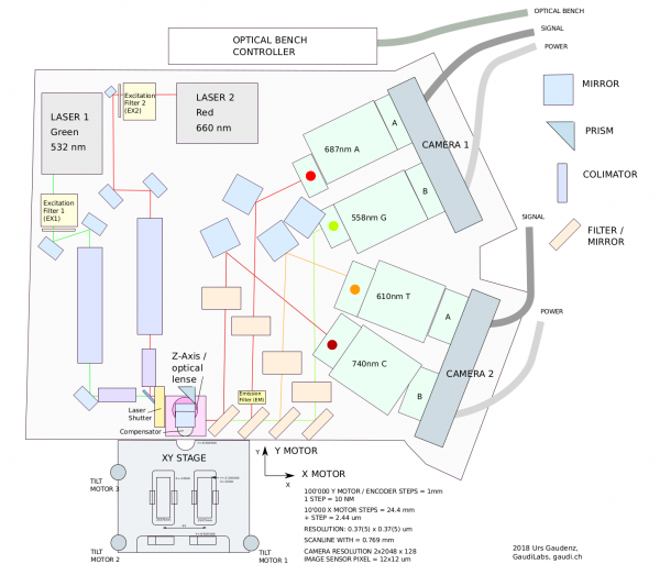
HiSeq2000 Optical Assy
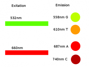
Excitations and emission wavelength.
| Path | Wavelength Range |
|---|---|
| G | 540 - 575 nm |
| T | 580 - 640 nm |
| A | 650 - 710 nm |
| C | 710 - 770 nm |
| Component | Filter range |
|---|---|
| Filter Mirror f17 | 500-600 nm |
| Filter Mirror f5 | 465-650 nm |
| Filter Mirror f16 | 425-570 nm |
| Filter f13 | 710-770 nm |
| Filter f12 | 580-640 nm |
| Filter f6 | 540-575 nm |
| Motorzed Filter | 675-695 nm |
[Analytical Channels]
Channel1 = Grn
Channel2 = Red
[Sequencing Channels]
Channel1 = C
Channel2 = A
Channel3 = T
Channel4 = G
| Path | SensorPath | LaserPath | ExcitationPosition | EmissionPosition | ChromaticCompensatorPosition |
|---|---|---|---|---|---|
| Analytical Channel Grn | 1 | 1 | OpenBandPassPosition | Filter.610-60 | Beadchip |
| Analytical Channel Red | 2 | 2 | OpenBandPassPosition | Filter.687-20 | Beadchip |
| Analytical Channel Reflective | 2 | 2 | OD2.5 Only Ex 2 | Open | Open |
| Analytical Channel Reflective Autocenter | 2 | 2 | OD2.5 Only Ex 2 | Open | Open |
| Analytical Channel Emissive | 1 | 1 | OD1.0 ETF like scanning | Filter.610-60 | Beadchip |
| Sequencing Channel A | 2 | 2 | OpenBandPassPosition | Filter.687-20 | Sequencing_AC |
| Sequencing Channel T | 1 | 1 | OpenBandPassPosition | Filter.610-60 | Sequencing_GT |
| Sequencing Channel G | 2 | 1 | OpenBandPassPosition | Filter.558-32 | Sequencing_GT |
| Sequencing Channel C | 1 | 2 | OpenBandPassPosition | Filter.740-60 | Sequencing_AC |
| Sequencing Channel Reflective | 2 | 2 | OD2.5 Only Ex2 | Open | Open |
| Sequencing Channel Emissive | 1 | 2 | OpenBandPassPosition | Filter.740-60 | Open |
Using the HiSeq2000 as aFluorescent Scanning Microscope
With many of the commands known it is possible to use the HiSeq2000 as a transmission or fluorescent scanning microscope. We developed a simple control software based on PureData to send commands to the HiSeq control hardware and get images from the scanning microscope. To view, set-up and read the scanner cameras we used HCImage software and TDIScan tool both available for free from Hamamatsu.
Downloads: https://hcimage.com/download/
https://dcam-api.com/downloads/ DCAM-API v15.10.4787
http://www.gaudi.ch/GaudiLabs/wp-content/uploads/HiSeq2000PureData.zip
Bright filed transmission microscope scans
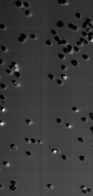
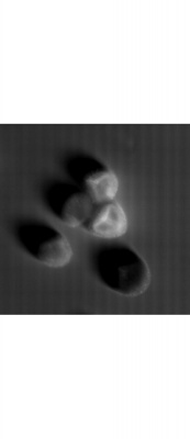
An power LED was mounted on the XY table, facing up for transmission microscopy. Images can be scanned with a 0.35 um resolution and in long, 0.7 mm large bands. Some pictures show several bands fitted together using ImageJ. The original images are in 16 bit grayscale TIFF format.
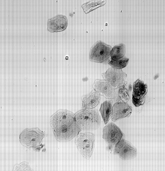
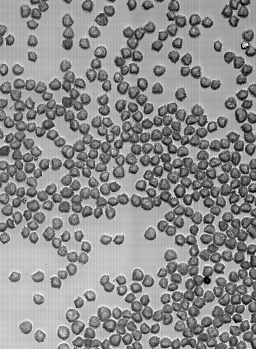
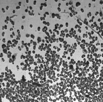
Check Cells, Lycopodium clavatum, Pollen in bight field mode
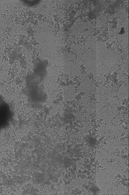

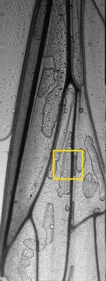
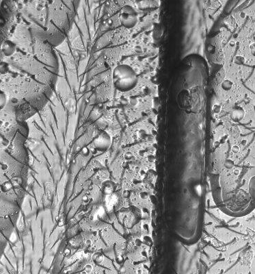
Large scale scan of yeast cells, daphnia, gep wing, Zoom shows detail
Fluorescent microscope scans
Using the laser and the filers, florescent samples can be scanned. We used different dyes that were suitable for the excitation and emission wavelength of the system.
Dyes:
- Nile Red
- Erythrosin B
- Glow stick chemistry
- fluorescent microbeads

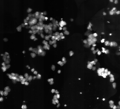
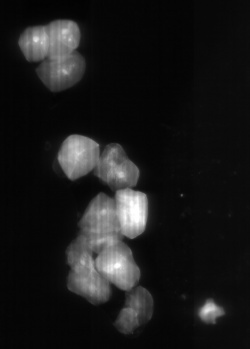
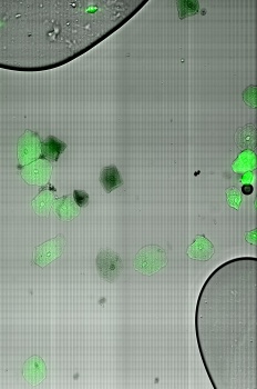
Microbeads 0.5um, Fluorescently stained check cells, zoom


Lycopodium with fluorescent dye, Lycopodium zoom, large scale scann, brightfield overlay with fluorescent image
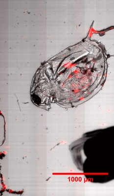
Daphnia with fluorescent micro-beads
Link to full resolution image:
http://www.gaudi.ch/GaudiLabs/wp-content/uploads/DaphniaCompositeScaleCrop.tif
Initialization Sequence for use with PureData sketch to scann (yes, we need a better software):
(HiSeq Control Software must be installed on Windows Vista)
 Boot Computer
 Turn on HiSeq2000
 Wait for all ports to initialize (DoNotEject drive to show up)
 Start HiSeq Control Software to initialize machine
 Start Windows Task Manager, go to Process window and "End Process" "HiSeqControlSoftware.exe"
 Start HCImageLive
 Choose Camera
 Start "Live"
 Set Exposure

 On PureData "HiSeq3"
 Open Ports
 Set X-Motor Position
 Set Y-Motor Position
 Home all 3 Tilt Motors
 Set Tilt Motor Encoders to zero
 Set Tilt Motos to "middle position", looking at Live Image, try to focus while moving up stage with Tilt Motors
 Use Z-Drive to fine tune focus
 Exit HCImageLive

 Start TDI Scan Software
 Set Sensor Mode to "TDI"
 Set "Line Bundle Height" to 2000
 Set "Repeat" to 4
 Set Trigger Source to "External"

 In PD:
 Set "Y-Motor Speed" to 0.16
 Set "TDI Arm Lines" to 8000
 Hit "Y-Motor Position" bang
 Hit "Start Y-Scan" bang

 In TDI Scan Software hit "Sequencial"
 In PD hit "SCAN Automatic"

 You should get a scan image.
Links and Information
Illumina Next Level Sequencing:
https://www.youtube.com/watch?v=womKfikWlxM&feature=youtu.be
Illumina Paired End Sequencing for Dummies:
https://kscbioinformatics.wordpress.com/2017/02/13/illumina-sequencing-for-dummies-samples-are-sequenced/
Expert Videos:
https://www.youtube.com/playlist?list=PLKRu7cmBQlai-GUWeAN-eHD5xRcCXDW-D
HiSeq2000 support page:
https://support.illumina.com/sequencing/sequencing_instruments/hiseq_2000.html
HiSeq 2000 User Guide:
http://fantom.gsc.riken.jp/5/sstar/images/1/11/HiSeq2000_UserGuide_15011190_D.pdf
HiSeq Compatibility Chart:
https://support.illumina.com/content/dam/illumina-support/help/version_compatibility/Default.htm
Video of the scanning:
https://www.youtube.com/watch?v=tuD-ST5B3QA
Illumina Support:
Switzerland +41 565800000 +41 800200442
OpenSeq / Discussion
The goal is to make it work!
Let's discuss on the forum.. http://forum.hackteria.org/t/hiseq2000-next-level-hacking/325/1
- Where to get/buy the reagents and flow cells
- Hackquarium Lausanne got a similar machine and dissasembled it. We can get pointers from Gustavo on how to take it all apart!
- Muffatto there's a fluorescence microscope inside (afaik), the issue is to reduce it in size and still have it working
- Muffatto: erik from biocurious reverse engineered the chemistry of the system for BGI
- Bengt: Absolutely in on building an openseq kind of thing that can run original reagents. And then re-engineering the system for smaller/cheaper/simpler - even better if combined with an effort to make open reagents - but that is 2 tracks that can progress independently
How about making an Open Source Next Level Sequencing machine - OpenSeq.
Maybe a bit slower and smaller.. like 1 genome per day 🙂
Not sure a price tag of 500k euro is justified for such a machine...
Maybe similar to the iSeq100:
https://www.illumina.com/systems/sequencing-platforms/iseq.html
