Difference between revisions of "Gär Lämpli"
From Hackteria Wiki
(→diy-CAD | A Creative PCB design tool for Children-direct-to-manufacturing) |
|||
| Line 1: | Line 1: | ||
| − | |||
| − | |||
| − | |||
| − | |||
| − | |||
| − | + | Description coming soon.... | |
| − | + | == Experience from the first workshop at Dimension Plus LAB, TW == | |
| − | = | + | ==='''Prepare 400% scaled, printed, laminated and cut-out smd parts.'''=== |
| − | == | ||
| − | + | [[File:IMG_20170316_143454.jpg|400px]] | |
| − | + | [[File:diy_CAD_laminates.png|400px]] | |
| − | [ | + | Download the files from the [https://github.com/8BitMixtape/8Bit-Mixtape-NEO/blob/master/boards/NEO-Coconut/G%C3%A4rL%C3%A4mpli_laminates_kit.pdf github]. |
| − | == | + | ==='''Discuss the difference between the "schematic" representation and "physical" implementation'''=== |
| − | + | <gallery mode="packed-hover" heights=200px> | |
| + | File:17310868_10154677328464775_603617587_o.jpg | ||
| + | File:17349104_10154677329069775_999032446_o.jpg | ||
| + | File:garLampli_schematics.png | ||
| + | </gallery> | ||
| − | == | + | ==='''Start layouting and drafting the correct connections with pencil'''=== |
| − | + | <gallery mode="packed-hover" heights=200px> | |
| − | + | File:IMG_20170316_191934_HDR.jpg | |
| + | File:IMG_20170316_184405_HDR.jpg | ||
| + | File:17357049_120300002609345492_1510475951_o.jpg | ||
| + | </gallery> | ||
| − | + | we should add some sticky tape to fix them... | |
| − | === | + | ==='''Overlay with a transparency sheet and draw the circuit traces and pads'''=== |
| − | + | Make sure you take some photo of your layout to refer to the part's position later. | |
<gallery mode="packed-hover" heights=200px> | <gallery mode="packed-hover" heights=200px> | ||
| − | File: | + | File:IMG_20170316_191926_HDR.jpg |
| − | File: | + | File:17357625_10154677327379775_1617751417_o.jpg |
| − | File: | + | File:dusjagrs_garlampli.jpg |
| − | |||
| − | |||
| − | |||
| − | |||
| − | |||
| − | |||
| − | |||
| − | |||
| − | |||
</gallery> | </gallery> | ||
| − | ''( | + | ==='''Scan (or photo), scale it back down, print and etch the boards'''=== |
| − | + | Take a decent photo, check for reflections from lamps and stuff. Edit the photo in GIMP, to select all surrounding areas and invert the selection. Fill with FG (black), copy, create from clipboard -> new file. import in Inkscape, rescale to original size (some markings on the drawing would be great). Last edits can also be done in inkscape, like adding logos, version numbers, open source coconuts or defined drill holes, cut-layer etc... | |
| − | + | <gallery mode="packed-hover" heights=200px> | |
| + | Eschers_garlampli.jpg | ||
| + | File:Eschers_garlampli_gold.png | ||
| + | File:Eschers_garlampli_layout.png | ||
| + | </gallery> | ||
| − | + | ==='''Etch the boards or send it for manufacturing'''=== | |
| − | + | Panel, Pring and etch, or use pdf2gerber to send it for manufacturing | |
| − | = | + | <gallery mode="packed-hover" heights=200px> |
| + | File:Jessies_garlampli.jpg | ||
| − | + | File:Eschers_garlampli_layout2.png | |
| − | + | </gallery> | |
| − | |||
| − | |||
| − | |||
| − | |||
| − | |||
| − | |||
| − | |||
| − | |||
| − | |||
| − | |||
| − | |||
| − | |||
| − | |||
| − | |||
| − | |||
| − | |||
| − | |||
| − | |||
| − | |||
| − | |||
| − | |||
| − | |||
| − | |||
| − | |||
| − | |||
| − | |||
| − | |||
| − | |||
| − | |||
| − | |||
| − | |||
| − | |||
| − | |||
| − | |||
| − | |||
| − | |||
| − | |||
| − | |||
| − | |||
| − | |||
| − | |||
| − | |||
| − | |||
| − | |||
Revision as of 07:18, 12 April 2017
Description coming soon....
Contents
- 1 Experience from the first workshop at Dimension Plus LAB, TW
- 1.1 Prepare 400% scaled, printed, laminated and cut-out smd parts.
- 1.2 Discuss the difference between the "schematic" representation and "physical" implementation
- 1.3 Start layouting and drafting the correct connections with pencil
- 1.4 Overlay with a transparency sheet and draw the circuit traces and pads
- 1.5 Scan (or photo), scale it back down, print and etch the boards
- 1.6 Etch the boards or send it for manufacturing
Experience from the first workshop at Dimension Plus LAB, TW
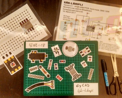
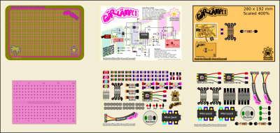
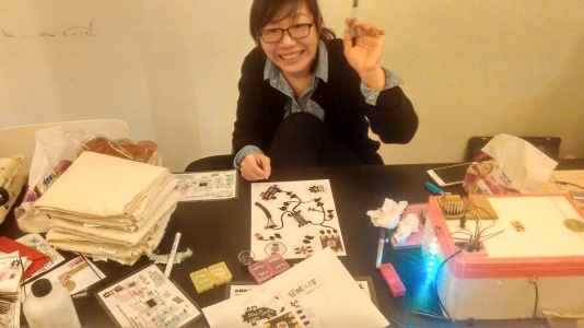
Prepare 400% scaled, printed, laminated and cut-out smd parts.
Download the files from the github.
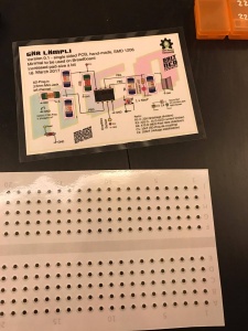
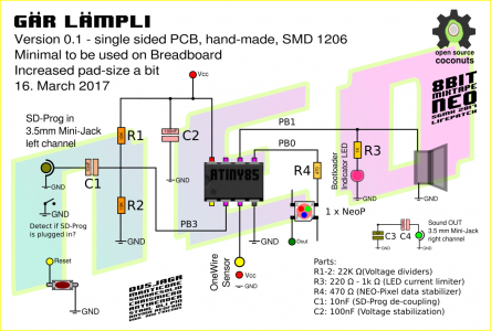
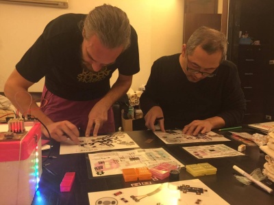
Discuss the difference between the "schematic" representation and "physical" implementation
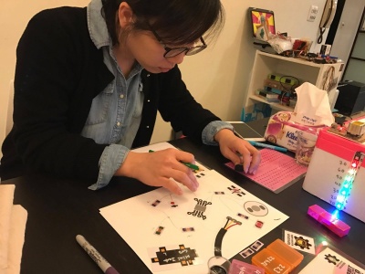
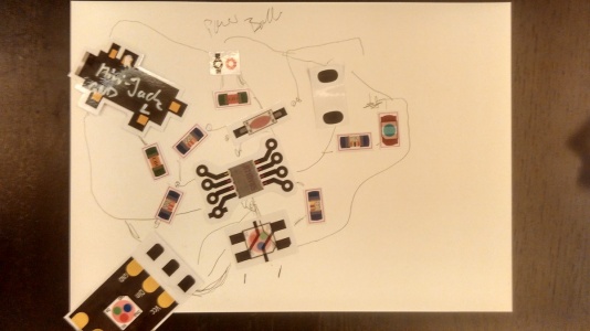
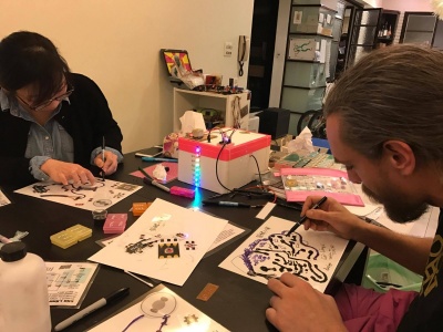
Start layouting and drafting the correct connections with pencil
we should add some sticky tape to fix them...
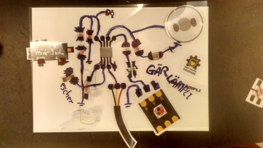
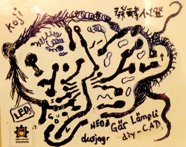
Overlay with a transparency sheet and draw the circuit traces and pads
Make sure you take some photo of your layout to refer to the part's position later.
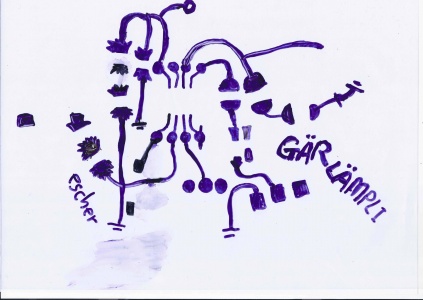
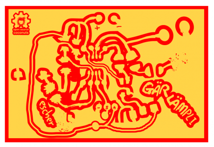
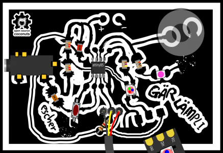
Scan (or photo), scale it back down, print and etch the boards
Take a decent photo, check for reflections from lamps and stuff. Edit the photo in GIMP, to select all surrounding areas and invert the selection. Fill with FG (black), copy, create from clipboard -> new file. import in Inkscape, rescale to original size (some markings on the drawing would be great). Last edits can also be done in inkscape, like adding logos, version numbers, open source coconuts or defined drill holes, cut-layer etc...
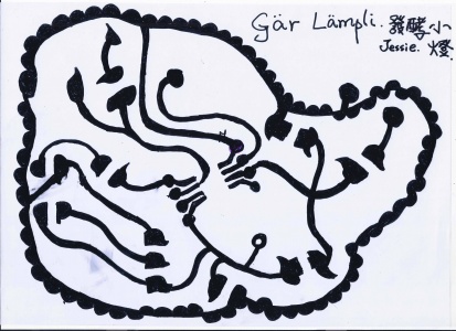
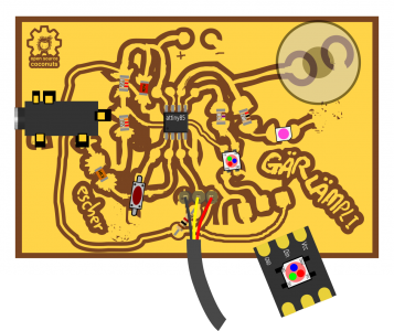
Etch the boards or send it for manufacturing
Panel, Pring and etch, or use pdf2gerber to send it for manufacturing
