DIY Microscopy Instruction (Serbian)
Contents
- 1 Instructions
- 1.1 0. Introduction and Materials
- 1.2 Parts/Material List
- 1.3 1. Conversion of the webcam Part A: Small enlargement
- 1.4 1. Conversion of the webcam Part B: Maximal enlargement
- 1.5 2. Construction of the platform
- 1.6 3. The light source
- 1.7 3.B Hacking the LEDs from the Webcam (to be documented)
- 1.8 4. Using the Microscope and Hunting for Microorganisms
Instructions

This is a translation of the original english/german article on DIY_microscopy. Feel free to contribute, change or add your own examples.
- Other languages available :
DIY Mikroskop Anleitung (Deutsch)
DIY Microscopy Instruction (Chinese)
DIY Microscopy Instruction (Portuguese)
DIY Microscopy Instruction (Spanish)
DIY Microscopy Instruction (Italian)
DIY Microscopy Instruction (Bahasa Indonesia)
DIY Microscopy Instruction (French)
DIY Microscopy Instruction (Japanese)
DIY Microscopy Instruction (български)
0. Introduction and Materials
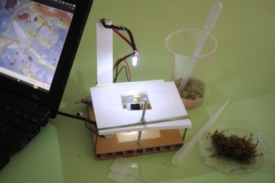
Making the DIY MICROSCOPE includes converting an ordinary webcam into a microscope. The webcam’s conversion can be quickly effected manually. The electronics remains unaltered, only the position of the lens is changed. A solid platform enables fixing and accurately focusing the tiny study objects. The objects are illuminated with a light-emitting diode (LED).
The DIY MICROSCOPE consists of three components, assembled in this sequence:
- Converted webcam
- Stable platform for observation
- Illumination with a light-emitting diode (LED)
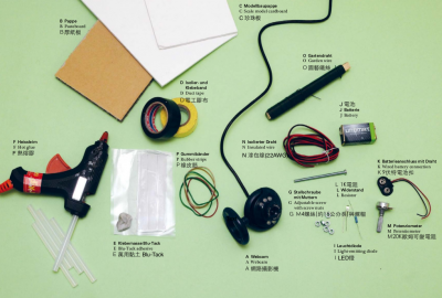
Parts/Material List
Basics
- 1 webcam
- Cardboard (thick) / wood, 20 x 30 cm
- Foamboard, 20 x 30 cm
- M4 adjustable screw, approx. 15 cm long, with fitting screw nuts
- Duct tape
- Blu-Tack adhesive
- Hot glue
- Rubberbands
Tools
- Cutter / sharp knife
- Screwdriver, small
- Hotglue gun
- (optional) Soldering iron
Optional external LED light source
- 1 switch
- 1 white light-emitting diode (LED)
- 1 battery (9V)
- 1 wired battery connection
- 1 resistor (1 k Ω )
- 1 potentiometer (20 k Ω )
- 30 cm insulated wire
- Garden wire
Microscopy and Micro-Hunting equipment
- Some transparent plastic cups
- Glass slides
- Petri dishes, made of plastic or glass
- Disposable pipettes
- Waterproof pen
- Small chrome steel spoon
- Tweezers
- Sealable plastic containers for samples
1. Conversion of the webcam Part A: Small enlargement
- A selection of standard webcams. Best suited are models allowing for manual adjustment of focus by turning the ring on the lens. The only solution is by trial and error.
- Before the camera is modified, it needs to be tested. For that it has to be connected to a computer, and additionally the necessary drivers have to be installed. Webcams run with Windows, Mac, or Linux.
- Already with this configuration the webcam can be used to inspect objects up close. You only need to screw out the lens a little and move closer to the object. A pocket lamp improves lighting conditions.
- Pointing the webcam on tiny objects produces surprising effects: Even without modifications one begins to see things hidden to the naked eye.
1. Conversion of the webcam Part B: Maximal enlargement
- Now we begin dismantling the webcam. The screws are removed. Partly such screws are hidden beneath labels or rubber caps. With a solid tool – in this case the screwdriver of a Swiss Army knife – the webcam ’s cover is removed.
- The appliance ’s interior can now be seen: it consists of optics and an electronic switch. We can do without the light-emitting diodes (LEDs). We shall later construct our own light.
- The optics is partially glued on. By careful twisting we can detach it from the electronics. The optics’ outer ring (at the right of the picture) will no longer be used later. It only serves as decoration.
- With the use of a strong side cutter we cut through the plastic casing. Now the electronics including all wires and the USB cable can be removed from the casing.
- The webcam’s interior: on the left side of the picture we can see the internal microphone, which, however, is not needed for our project.
- Now we place the optics upside down on the fitting. It can no longer be screwed on and must therefore be firmly secured. The optics is attached with a piece of duct tape.
- To test the equipment we connect the modified webcam with the computer and point the lens towards the screen. Now the individual
RGB pixels on screen become visible.
2. Construction of the platform
- Using small lumps of Blu-Tack adhesive, the webcam is attached to a solid pasteboard of about 15 x 15 cm.
- The platform’s side wall consisting of scale model cardboard. With a pencil we draw the height of the lens on it and cut off the cardboard along that line. We use hot glue for pasting.
- Using a carpet cutter, we cut a rectangular opening into another piece of scale model cardboard. This piece too is attached with hot glue.
- The adjustable screw requires a hole. We attach the screw nut right at the top with a small drop of hot glue. Then we insert the adjustable screw. It must reach down to the lower platform.
- Rubber bands provide more stability to the platform. With the screw the scale model board can now be moved up and down by a few millimeters.
3. The light source
- Our microscope also has a light source in the form of a light-emitting diode (LED). The lighting can be easily produced by oneself.
- In this easy way, the wires can be twisted together. But it is safer if they are solded on.
- The centimeters long feed of our light source is wrapped with garden wire. The wire thus becomes pliable and later can be attached in any position.
- The light source, potentiometer and battery are attached to our construction with hot glue. Our DIY MICROSCOPE is ready for use.
3.B Hacking the LEDs from the Webcam (to be documented)
- Coming soon
4. Using the Microscope and Hunting for Microorganisms
- The USB cable of the converted webcam is connected to the computer. Now we can begin with our examinations.
- The study objects are placed on a glass slide and can be shifted by hand. The microscope’s focus is regulated by the adjustable screw.
- As with a professional microscope, with our DIY tool we are able to take electronic photos and even films. Photos and films are digitally available, can be further processed and of course be easily published on the Internet.


